 Electromagnetism · Pre-compliance Testing
A practical alternative to full-chamber testing — how current clamps capture differential and common mode currents, translate them into estimated field strength, and help engineers identify emission sources before they reach the lab.

Radiated emissions testing is essential for achieving electromagnetic compatibility compliance. This testing ensures electronic devices don't interfere with one another by emitting excessive electromagnetic energy. Traditionally, specialized EMC chambers are used for this — employing antennas to measure radiated fields. However, an EMC current clamp provides a practical alternative, allowing engineers to estimate radiated emissions without a full chamber setup.
This tool is particularly valuable during the design and pre-compliance phases, where you need rapid debugging without committing to chamber time. This article covers the principles of the EMC current clamp, its operational mechanism, and the methodology for estimating radiated emissions from measured currents.
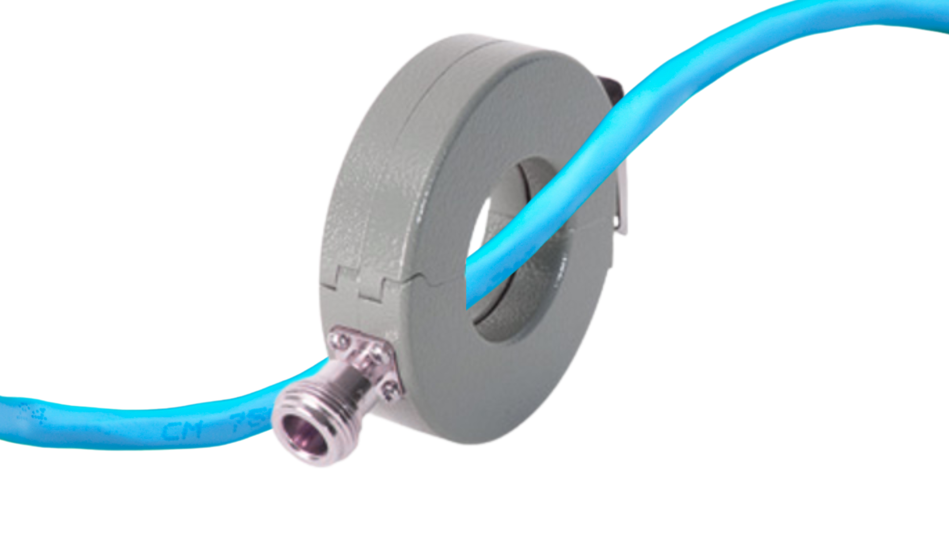
An EMC current clamp is a diagnostic tool used to measure the current flowing through a cable — and that current correlates directly to radiated emissions. It resembles a hinged ring with a magnetic core and a pickup coil wound around it. A connector links the clamp to a spectrum analyzer.
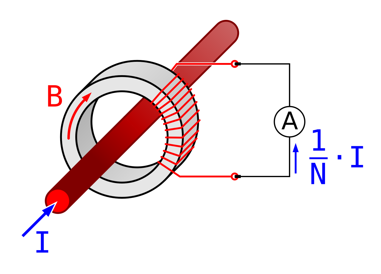
Basic operation of a current transformer — By Biezl, CC BY 3.0
The clamp encircles the cable from the device under test (DUT), capturing electromagnetic currents without interrupting the circuit. This non-invasive technique is well suited to troubleshooting and pre-compliance evaluations.
The clamp operates on electromagnetic induction. As current flows through the cable, it generates a magnetic field that induces a voltage in the pickup coil. That voltage is transmitted to the spectrum analyzer, which displays it relative to the probe's transfer impedance.
The resulting signal provides insight into the current's magnitude and frequency content — the foundation for estimating radiated emissions. Unlike direct field measurement in a chamber, the current clamp focuses on conducted currents, providing an indirect but effective way to predict radiation before you're standing in front of an antenna.
To estimate radiated emissions accurately, you need to understand how differential and common mode currents behave in a cable — because they contribute very differently to electromagnetic radiation.
In a two-wire system, differential mode current flows out through one conductor and returns through the other. Ideally, with perfect cable coupling, these currents cancel — net current is zero. In practice, imperfections such as poor shielding or physical separation between the wires prevent full cancellation, leaving residual current that may radiate.
Common mode current flows in the same direction through all conductors, returning via an unintended path such as a chassis or earth ground plane. In a three-wire system, common mode current may loop through the DUT and return via the chassis. This current does not cancel within the cable — it creates a large, uncontrolled radiating loop and is the primary source of radiated emissions.
When the clamp encircles all conductors, it measures the net current — the portion that does not cancel. This uncanceled current, whether from differential mode leakage or common mode flow, is what drives radiated emissions. That's what makes the clamp such a powerful diagnostic tool.
Converting clamp measurements into an electric field estimate relies on a well-established equation that mirrors what an antenna would detect in a test chamber. The formula is:
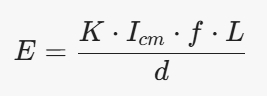
E — Electric field strength (V/m)
K — Constant (≈ 1.257 × 10⁻⁶ for simplified free-space calculations)
Icm — Common mode current (A) — the uncanceled current measured by the clamp
f — Frequency of the current (Hz)
L — Length of the cable (m)
d — Distance from the cable to the measurement antenna (m)
The equation assumes the cable behaves as a radiating antenna. Field strength is proportional to current, frequency, and cable length — inversely proportional to the distance from the measurement point.
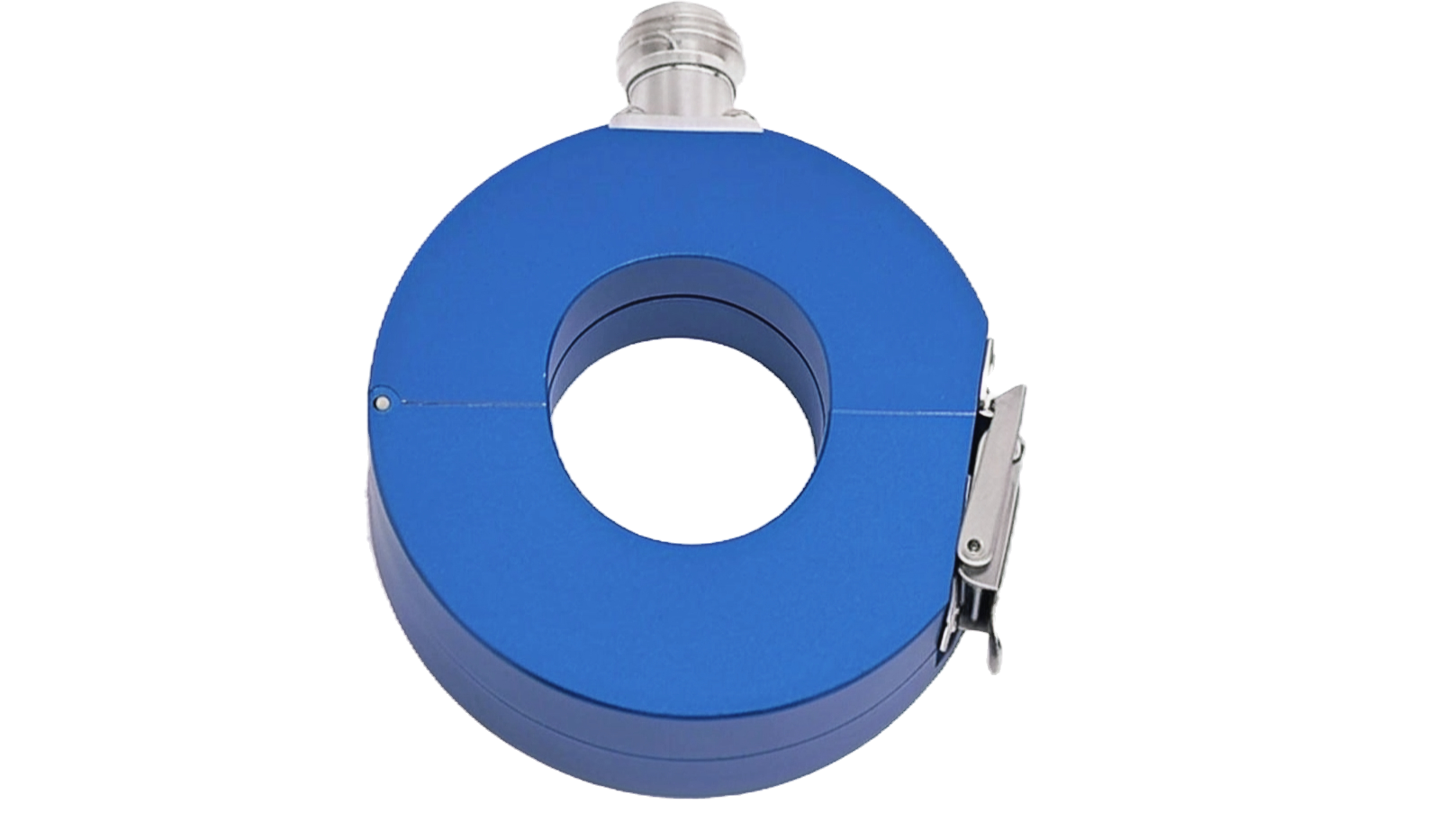
An RF current probe designed for efficient measurement and analysis of radio frequency currents.
As a concrete example: a 1-meter power cable with a clamp-measured current of 10 µA at 40 MHz, antenna 3 meters away, yields E = 167.6 µV/m. That result can be compared directly against applicable EMC limits to assess compliance risk.
Higher frequencies amplify emissions, and longer cables increase the radiating loop size — both are critical factors when deciding where to focus EMC design effort.
Accurate current measurement requires understanding the probe's transfer impedance — a parameter provided by the manufacturer. It represents the voltage output of the probe relative to the current flowing through the cable, expressed in ohms:
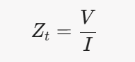
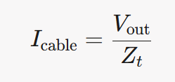
To calculate the actual current in the cable from the measured voltage:
Transfer impedance varies with frequency and is typically given as a chart or table in the probe's datasheet.
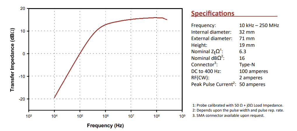
Fischer F-33-1 Current Monitoring Probe — Transfer Impedance characteristic across frequency.
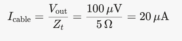
For instance, if a probe has a transfer impedance of 5 Ω at 40 MHz, and the spectrum analyzer measures 100 µV:
This current can then be fed into the radiated emissions equation to estimate field strength. Always refer to the probe's transfer impedance chart — the formula only gives accurate results when you use the correct Zt at the relevant frequency.
An effective measurement setup for a two-wire system follows this sequence:
Connect the DUT to a power source. A direct power connection is sufficient — the clamp measures cable currents independently of the power line's impedance.
Encircle the power cable. Ensure the clamp surrounds all relevant conductors. For a two-wire system, include both wires to measure the net current. Confirm the clamp is fully closed to maximize magnetic coupling.
Connect to the spectrum analyzer via coaxial cable. No additional termination is typically required.
Monitor the display as the DUT runs. Observe voltage peaks at varying frequencies. Measure each peak and convert voltage to current using the probe's transfer impedance at that frequency.
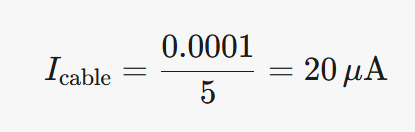
For example, if the spectrum analyzer records V = 100 µV at 40 MHz with Zt = 5 Ω:
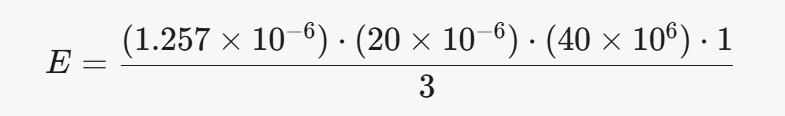
Now apply that current in the radiated emissions equation. With Icable = 20 µA, f = 40 MHz, L = 1 m, d = 3 m:
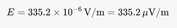
The calculated field strength of 335.2 µV/m at 3 meters exceeds the limits of every major standard:
FCC Class B: Limit is 100 µV/m at 3 m — calculated value is 335.2 µV/m. Exceeds by ~10 dB.
FCC Class A: Limit is 90 µV/m at 10 m — adjusted value is 100.56 µV/m. Exceeds.
MIL-STD 461: Limit is 16 µV/m at 1 m — adjusted value is 1005.6 µV/m. Exceeds significantly.
To improve harmonic detection, reposition the clamp along the cable while monitoring the analyzer. This reveals current peaks caused by standing waves at specific frequencies. At 40 MHz (λ ≈ 7.5 m), peaks may appear every 1.875 m. Identify the most prominent harmonics, compute the current at each using the transfer impedance chart, and trace emission sources in the DUT — unfiltered switching circuits, inadequate return paths, poorly routed cables.
Small currents generate significant emissions. High-frequency currents as low as 5–8 µA at 30–100 MHz can approach or exceed FCC Part 15 and CISPR 32 Class B limits (~40 dBµV/m at 3 m), depending on cable length and geometry. Calculate the radiated field for each measured current and compare it against the relevant standard limit directly.
The current clamp is most useful during the pre-compliance phase — when you're still iterating on the design. By clamping different cables or sections of the DUT, you can identify where emissions originate: a noisy power line, an unshielded signal cable, or a return path with a slot cut through it. That narrows the design fix before you commit to chamber time.
The method has real limitations. The equation assumes simplified geometry — straight cables in free space. Real setups involve complex geometries, nearby conductors, and environmental factors that influence radiation patterns. The clamp measures conducted current, not the radiated field directly, so the estimate is an approximation. For formal certification, chamber testing remains the standard. The clamp gives you a reliable starting point.
The EMC current clamp connects conducted current measurements to radiated field estimates through straightforward physics. Used correctly, it lets you catch emission problems at the bench — before they find you in the chamber.
An EMC Design Audit reviews your schematic and PCB layout before fabrication — identifying return path gaps, filter placement errors, and stackup decisions that turn into failures at the test house. Report delivered in 10 business days.