Adding a filter to an I/O connector isn't the end of the story — it's the beginning of an impedance matching problem. The wrong topology in the wrong impedance environment won't just underperform. It can make emissions worse.

EMC filters are the interface between your circuit and the outside world. At every connector where a cable leaves or enters the board, you have a choice: control the field propagation at that boundary, or let the cable carry whatever field energy exists on the conductor out into the environment — where it becomes a radiated emission or a conducted susceptibility path.
Most engineers understand that filters go at connectors. Fewer understand that the choice of filter topology is not arbitrary — it must be matched to the source and load impedances of the specific interface, or the filter will not achieve its rated insertion loss in practice.
A filter's datasheet insertion loss is measured under standardised 50Ω source and load conditions. Your actual circuit is not 50Ω. The cable is not 50Ω. The impedance environment seen by the filter at your specific interface will differ from test conditions — sometimes dramatically. A filter that shows 40 dB insertion loss in a 50Ω/50Ω test setup may deliver 10 dB or less in the actual circuit. Choosing the right topology mitigates this mismatch.
The simplest approach: a series inductor increases impedance to high-frequency noise in the signal path, while a shunt capacitor diverts noise to the return plane. Works well when source and load impedances are well-defined and stable. In low-impedance environments, series inductors are more effective; in high-impedance environments, shunt capacitors work better. Do not use blindly — the impedance environment must be assessed first.
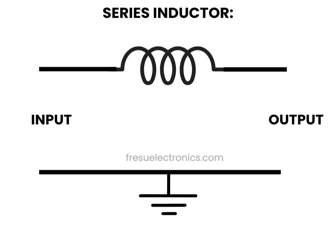
Series Inductor Filter.
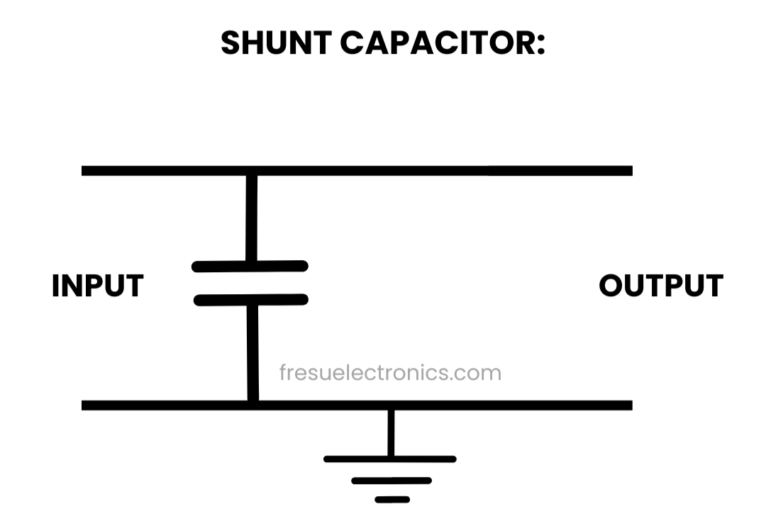
Shunt Capacitor Filter.
A shunt capacitor followed by a series inductor. This topology works best when the source impedance is low — it first diverts high-frequency noise to ground, then blocks what remains with the series inductor. Common at power input interfaces where the source is a low-impedance supply rail.
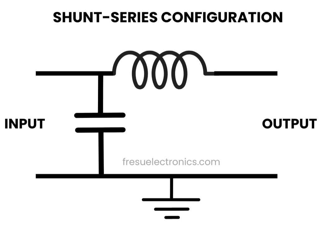
Shunt-Series Filter.
A series inductor followed by a shunt capacitor. Preferred when load impedance is low — the inductor blocks noise from reaching the load, and the capacitor diverts what passes through to ground. Useful at the output of switching regulators driving low-impedance loads.
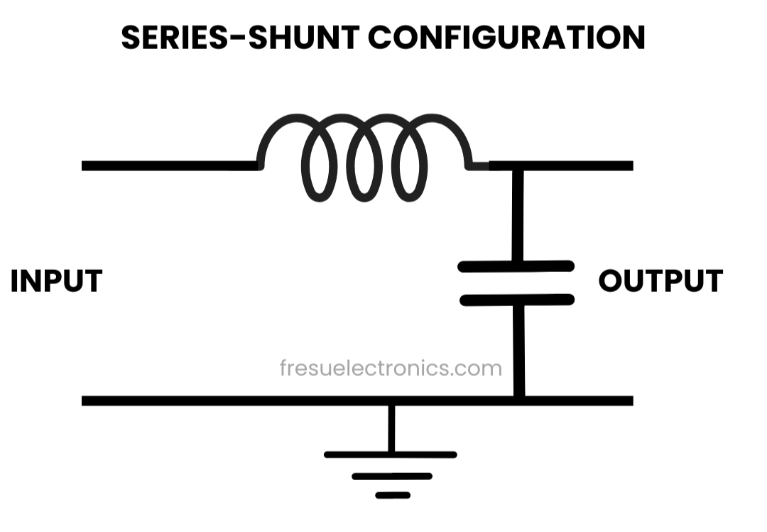
Series-Shunt Filter.
Two shunt capacitors with a series inductor between them. Provides higher insertion loss than L-filters and works well when both source and load impedances are high. The most effective topology for conducted emissions on high-impedance signal lines, but requires careful component selection to avoid resonance peaks that can amplify noise at specific frequencies.
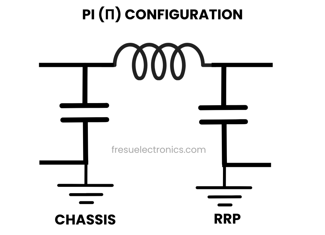
Pi (π) Filter Configuration.
Two series inductors with a shunt capacitor between them. Optimised for low source and load impedances. Common in power line filtering where the supply and load are both low impedance. Like the π-filter, component tolerances and parasitic elements must be controlled to avoid undesirable resonance behaviour.
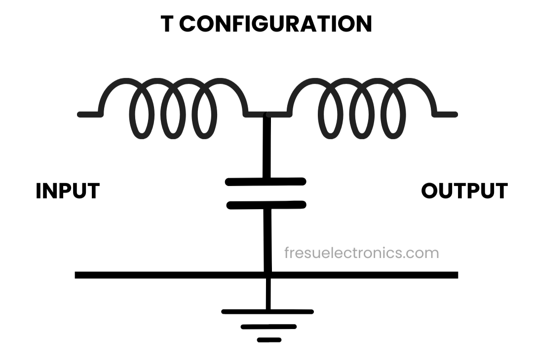
T-Filter configuration
A filter in the wrong location does not filter. The fundamental rule: filters must be placed at the boundary between the inside and outside of the system — at the connector, not somewhere on the board interior. A filter placed 50mm from the connector with an unfiltered trace running to the connector shell is not filtering the cable. It is filtering the PCB trace between the filter and the connector, while the cable radiates freely.
A filter that isn't at the boundary isn't a filter. It's a component with a false sense of security around it.
Most EMC failures involve common-mode current — noise that appears on all conductors of a cable simultaneously and returns through a parasitic path (typically chassis or earth). Standard LC filters address differential-mode noise well but provide limited common-mode attenuation. For common-mode filtering, you need common-mode chokes: inductors wound so that differential currents cancel in the core while common-mode currents see high impedance. In most practical designs, both filter types are needed — the π or T topology handles differential-mode, and a common-mode choke handles the antenna-mode current that drives radiated emissions.
Work directly with Dario to identify EMC risks at the design stage — before a €15,000–40,000 chamber session reveals issues that require a respin.
Get articles before they're published